Within the approximation represented by geometrical optics, light is understood to travel out from its source along straight lines or rays. The ray is simply the path along which energy is transmitted from one point to another in an optical system. The ray is a useful, although abstract, construct; perhaps the best approximation to a ray of light is a pencil-like laser beam. When a light ray traverses an optical system consisting of several homogeneous media in sequence, the optical path is a sequence of straight-line segments. The laws of geometrical optics that describe the subsequent direction of the rays are succinctly stated as:
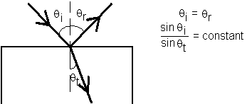
Law of Reflection: When a ray of light is reflected at an interface dividing two uniform media, the reflected ray remains within the plane of incidence, and the angle of reflection equals the angle of incidence. The plane of incidence includes the incident ray and the normal to the point of incidence.
Law of Refraction (Snell's Law): When a ray of light is refracted at an interface dividing two uniform media, the transmitted ray remains within the plane of incidence and the sine of the angle of refraction is directly proportional to the sine of the angle of incidence.
These laws can be visually seen in the following figure
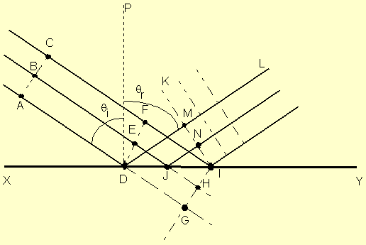
The figure illustrates Huygens' construction for a
narrow, parallel beam of light to prove the law of reflection. Huygens'
principle must be modified to accommodate the case in which a wavefront, such as
AC, encounters a plane interface, such as XY, at an angle. Here
the angle of incidence of the rays AD, BE, and CF relative
to the perpendicular PD is i. Since points along the plane
wavefront do not arrive at the interface simultaneously, allowance is made for
these differences in constructing the wavelets that determine the reflected
wavefront. If the interface XY were not present, the Huygens construction
would produce the wavefront GI at the instance ray CF reached the
interface at I. The intrusion of the reflecting surface, however, means
that during the same time interval required for ray CF to progress from
F to I, ray BE has progressed from E to J and
then a distance equivalent to JH after reflection. Thus a wavelet of
radius JH centered at J is drawn above the reflecting surface.
Similarly, a wavelet of radius DG is drawn centered at D to
represent the propagation after reflection of the lower part of the beam. The
new wavefront, which must now be tangent to these wavelets at points M
and N, and include the point I, is shown as KI in the
figure. A representative reflected ray is DL, shown perpendicular to the
reflected wavefront. The normal PD drawn for this ray is used to define
angles of incidence and reflection for the beam. The construction clearly shows
the equivalence between the angles of incidence and reflection.
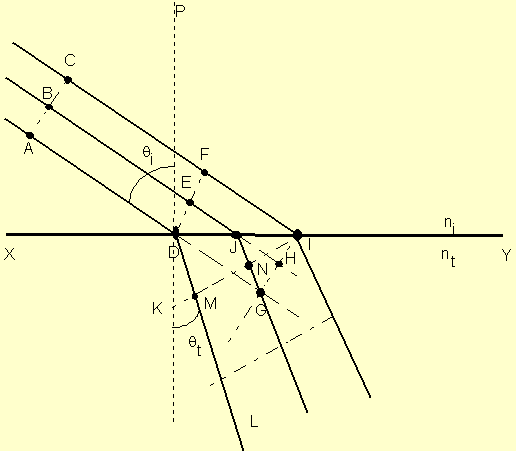
Here we must take into account a different speed of light in the upper and lower media. If the speed of light in vacuum is c, we express the speed in the upper medium by the ratio c/ni, where ni is the refractive index. Similarly, the speed of light in the lower medium is c/nt. The points D, E and F on the incident wavefront arrive at points D, J and I of the plane interface XY at different times. In the absence of the refracting surface, the wavefront GI is formed at the instant ray DF reaches I. During the progress of ray CF from F to I in time t, however, the ray AD has entered the lower medium, where the speed is different. Thus if the distance DG is vit, a wavelet of radius vtt is constructed with center at D. The radius DM can also be expressed as
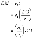
Similarly, a wavelet of radius
(ni/nt)JH is drawn centered at J. The
new wavefront KI includes point I on the interface and is tangent
to the two wavelets at points M and N. The geometric relationship
between the angles i and
t, formed by the representative
incident ray AD and refracted ray DL, is Snell's law, which
may be expressed as
![]() (6.1)
(6.1)
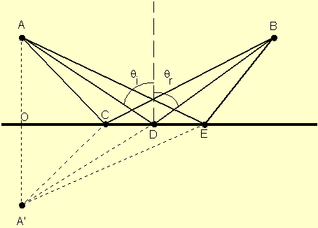
Three possible paths from A to B are
shown. Let's look at the arbitrary path ACB. If point A' is
constructed on the perpendicular AO such that AO = A'O, the
right triangles AOC and A'OC are equal. Thus AC = A'C and
the distance traveled by the ray of light from A to B via C
is the same distance from A' to B via C. The shortest
distance from A' to B is obviously the straight line A'DB,
so the path ADB is the correct choice taken by the actual light ray.
Geometry shows that for this path, i =
r. Also note that to maintain A'DB as a single
straight line, the reflected ray must remain within the plane of
incidence.
We can also prove the law of refraction. If the light travels more slowly in the second medium, light bends at the interface so as to take a path that favors a shorter time in the second medium, thereby minimizing the overall transit time from A to B.
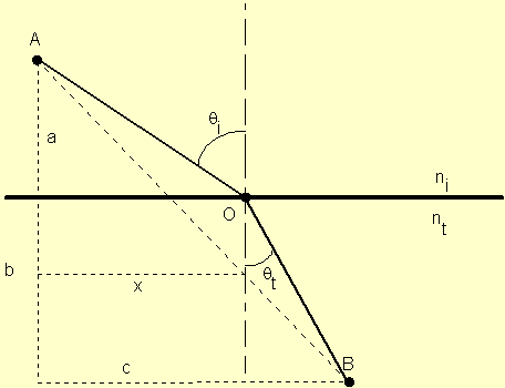
Mathematically, we are required to minimize the total time
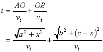 (6.2)
(6.2)
Since other choices of path change the position of the
point O and therefore the distance x, we can minimize the time by
setting ![]() :
:
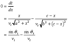 (6.3)
(6.3)
where the last step used the relationships shown in the figure. Introducing the refractive indices of the media, we arrive at Snell's law
![]() (6.4)
(6.4)
Fermat's principle, like that of Huygens, required refinement to achieve more general applicability. Situations exist where the actual path taken by a light ray may represent a maximum time or even one of many possible paths, all requiring equal time. As an example of the latter case, consider light propagating from one focus to the other inside an ellipsoidal mirror, along any of an infinite number of possible paths. Since the ellipse is the locus of all points whose combined distances from the two foci remain constant, all paths are indeed of equal time. A more precise statement of Fermat's principle, which requires merely an extremum relative to neighboring paths, may be given as follows: The actual path taken by a light ray in its propagation between two given points in an optical system is such as to make its optical path equal, in the first approximation, to other paths closely adjacent to the actual one.
With this formulation, Fermat's principle falls in the class of problems called variational calculus, a technique which determines the form of a function that minimizes a definite integral. In optics, the definite integral is the integral of the time required for the transit of a light ray from starting to finishing points.
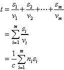 (6.5)
(6.5)
where the summation is called the optical path length traversed by the ray. Clearly for an inhomogeneous medium where n is a function of position, the summation must be changed to an integral
Since the optical path length is related to the time, we can restate Fermat's principle again as a light ray in going from point A to point B must traverse an optical path length that is stationary with respect to variations of that path.
Consider the specular reflection of a single light ray
from the x-y plane. By the law of reflection, the reflected ray remains
within the plane of incidence, making equal angles with the normal at the point
of contact. If the path is resolved into components, it is clear that the
direction of the incident ray is altered only by reflection along the z
direction, and then in such a way that its z component is simply
reversed. If the direction of the incident ray is described by its unit
vector ![]() ,
then the reflection causes
,
then the reflection causes
![]() (6.6)
(6.6)
It follows that if a ray is incident from such a direction as to reflect sequentially from all three coordinate planes, then
![]() (6.7)
(6.7)
and the ray returns precisely parallel to the line of its original approach. A network of such corner reflectors ensures the exact return of a beam of light.
Last updated: July 13, 1997
Comments to: mailto:%20D-Suson@tamuk.edu